
A GPS disciplined oscillator was a goal of mine for a long time now, i obtained a Motorola oncore UT+ timing GPS module off ebay along with a proper outdoor timing GPS helical antenna for about $40 some time ago.
This module outputs 1pps along with NMEA serial data, problem with this is how do you turn 1pps to 10MHz with low jitter?
A Phased Lock Loop would never work with a 10,000,000 divisor so i set out to design something, what i came up with was an oven controlled oscillator with a frequency set pin, a CPLD, and a DAC to count of number of cycles the OCXO puts out and compare it to 100 rising edges of the 1PPS output, if over 1,000,000,000 than it would tune the control voltage down, if less than it would tune it up.
This works fine in theory but in practice i learned quickly that im A) not a very good CPLD programmer, B) very fast rising edges on home-made PCBs cause all sorts of trouble
I gave up on this project to focus on other things when i came across Scullcom Hobby Electronics’ video on how to make a 10mhz reference using a uBlox NEO-7 location GPS’s time out pulse set for 10MHz.
I got one of these units off ebay for $7 shipped complete with an active antenna, a breakout PCB with a 3.3v regulator, backup battery and allegedly an EEPROM for configuration, but it appears as if it loses configuration data on power loss hinting to me that the EEPROM is just to prevent a cold start on startup, just holding sat data.
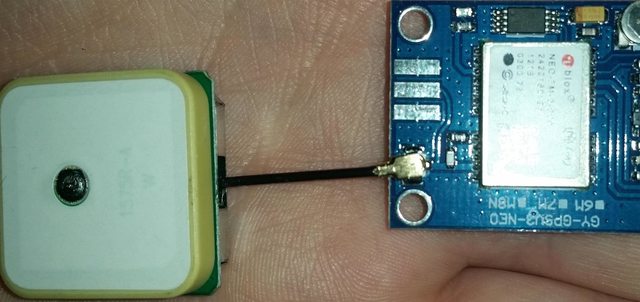
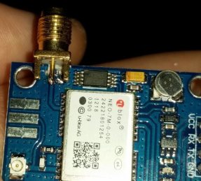
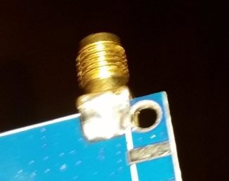
I got started by removing the resistor and LED from a reasonably laid trace that appears to be fine for the frequencies of interest, and placing on an SMA connector
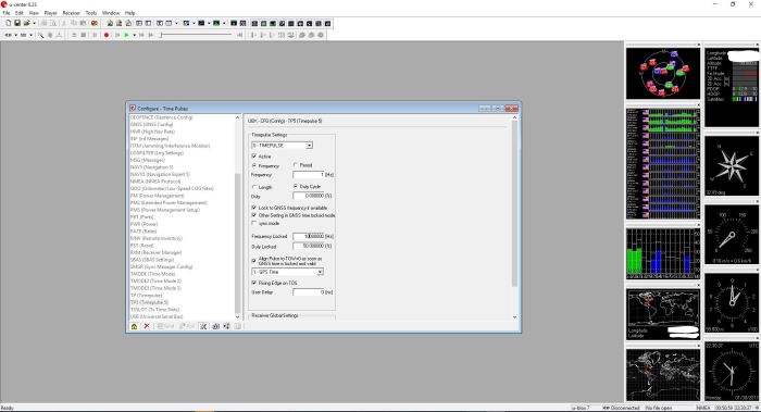
Configuring the uBlox module with the u-center tool was very easy as shown below.
But the news is not all good, the output, despite having an average frequency of exactly 10MHz, had quite a bit of jitter
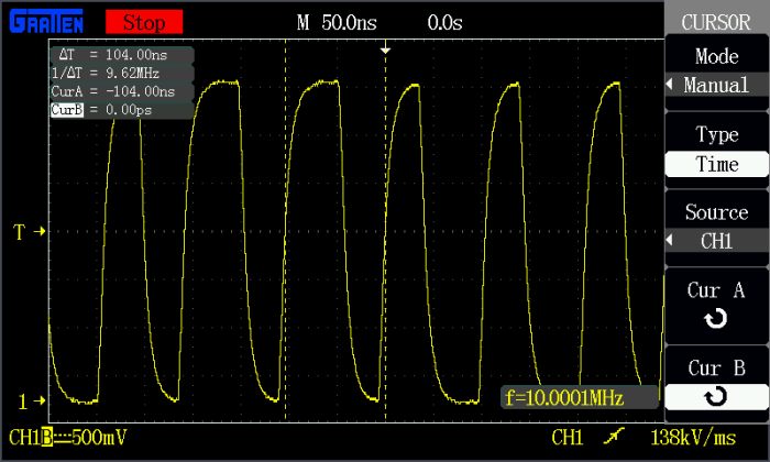
The jitter looks all the world to me like a system trying its darndest to divide a clock that is not easily divisible, this would be fine for calibrating frequency references but it’s not good for acting as a reference for test equipment or as a clock reference for a project.
My first idea was to create something called a jitter attenuator, 10MHz single chip solutions to this are hard to find and even harder to obtain. The next option was to create one from scratch, this is done in my case by using a PLL to multiply the 10MHz to 100MHz than divide it back down to 10MHz using a fairly high loop filter.
My design is below.
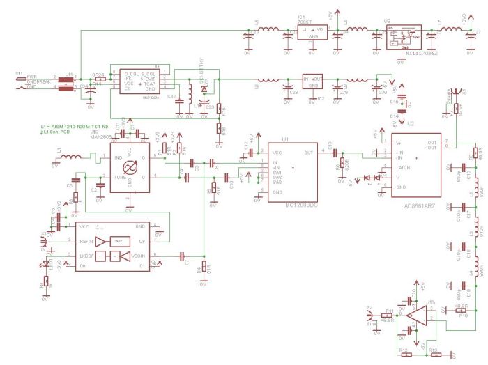
This design also adds in a low pass filter to transform the square wave to a sine wave to have both a square and sine wave output. This is not optimized, not properly calculated out and many values are missing. this is because this has turned into a bit much for what needs to be done.
So i started looking in to other routes, i noticed in the uBlox software the maximum set frequency was 24MHz, this lines up with the 48MHz timing clock from the GPS system itself, meaning the internal oscillator is either 24 or 48MHz, setting it to the maximum 24MHz i got a clock as shown below.
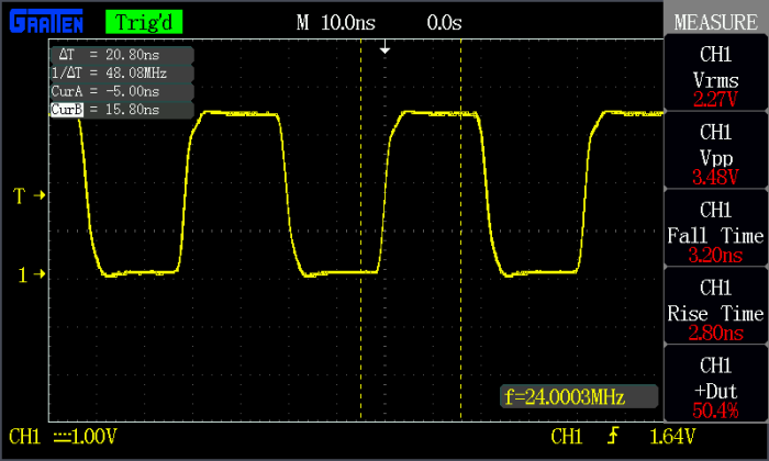
This clock is exceptionally stable with a duty of 50% and a reasonable and stable rise and fall time and no measurable deviation, my next plan is to get an any frequency generator like the Si5351A that has a built-in PLL and three separate output divisors.
A problem might arise as the Si5351A uses a minimum clock input of 25MHz, But i believe from reading the datasheet that 24MHz will work fine, granted some trial and error would have to be taken to find the proper divisors.
This method offers several benefits.
A) I don’t have to mess with making a PLL.
B) The output stability and jitter has already been characterized.
C) I can adjust the output frequency on the fly between an estimated 2.4 kHz and 192 MHz.
D) I get 3 separate and buffered outputs to do as i wish and can set different frequencies on each.
E) Code and libraries exist for the Si5351A for many different microcontrollers.
Seeing how cheap Si5351A boards are on Adafruit, this will be my next step.
Stay tuned!
Wait so what will i do with the Motorola Oncore UT+?
I think ill make my own home NTP server! … staytuned for that also!

This module will hold user-defined settings. After you SEND the changes you made to a particular page, you have to go to Configuration page and SEND that with User Defined selected.
Hope this helps.
LikeLike
It stores these changes in volatile memory as far as i’m aware even when i use send in the utility
LikeLike
It is stored in non-volatile memory. I’ve been using these for years.
NEO-6 Datasheet
1.15 Configuration
Once the module has started, the configuration settings can be modified with UBX configuration messages. The modified settings remain effective until power-down or reset. If these settings have been stored in battery-backup RAM, then the modified configuration will be retained, as long as the backup battery supply is not interrupted.”
u-blox 6 Receiver Description
5.3 Permanent Configuration Storage Media
The Current Configuration is stored in the receiver’s volatile RAM. Hence, any changes made to the Current Configuration without saving will be lost in the events listed in the section above. By using UBX-CFG-CFG/save, the selected configuration sub-sections are saved to all non-volatile memories available:
LikeLike
Oh i don’t remember that working for me, thank you, i will have to take another crack at it.
The project has been finished for a year i just have yet to have the time for a write up and i used a large battery backup for it but it’s nice to know i can omit that going forward.
but thanks for the comment!
LikeLike
Yes, after you save the changes you made to the configuration, you have to go to this other menu and SAVE to the non-volatile memory that is off-chip on the u-blox board, so it is a two-step operation.
LikeLike